

CHANNEL LETTER SIGNS · TECHNICAL BUYER GUIDE
How to Read a Channel Letter Wiring Diagram Before Installation
A channel letter wiring diagram should explain how individual letters, LED branches, cable exits and power supplies are coordinated for the approved project. Sign buyers and installation teams need a clear responsibility boundary: the drawing communicates the intended interface, while qualified local professionals complete and verify site electrical work.
- Match letter IDs, branch groups and cable exits to the approved drawing.
- Check the component record, power-supply reference and drawing revision.
- Agree the local electrical verification and handover responsibilities.
BUYER DECISION FRAMEWORK
Match the Drawing to the Supplied Sign
Read the drawing alongside the approved elevation, component labels and revision record. Reconcile mismatches before the affected installation work proceeds.
| Drawing reference | Compare with | Resolve before connection |
|---|---|---|
| Letter or sign ID | Approved elevation, physical label and packing reference | Repeated characters must be distinguishable. |
| Branch or sign group | Component schedule and identified letters | Confirm which supplied elements belong together. |
| Cable exit | Mounting drawing and actual site access | Refer mismatches to the responsible project parties. |
| Power-supply reference | Supplied component record and intended accessible location | Local professionals verify the final supply and connection requirements. |
| Revision and handover | Approved drawing and installer document package | Agree responsibility for final connections, protection and testing. |
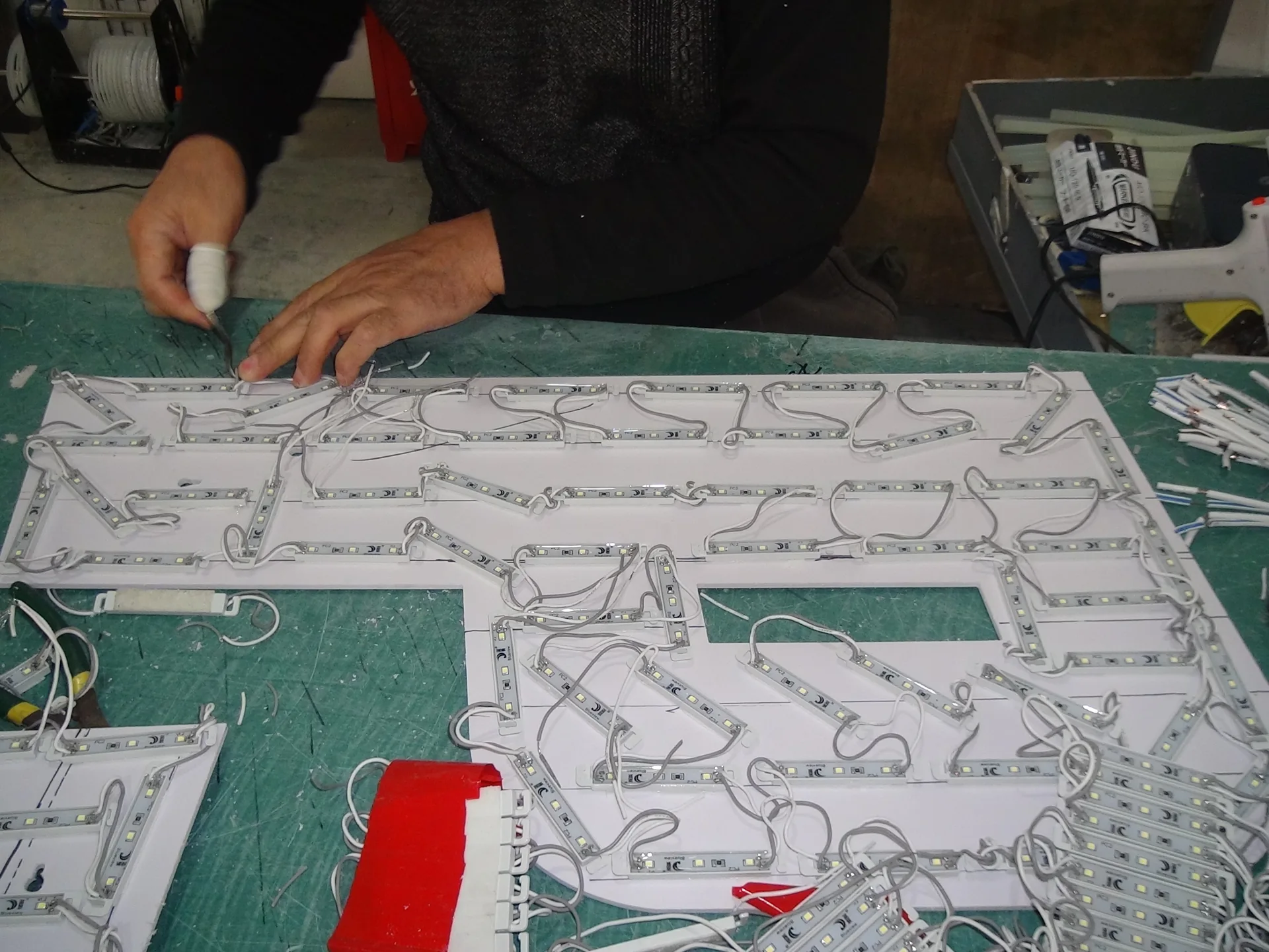
PROJECT INPUT
Factory-side information
A project drawing can identify sign components, cable exits and the intended connection interface.
- Identify sign groups and components
- Locate cable exits
- Review the power-supply location
BUYER DECISION
Local electrical verification
The final circuit, supply and installation must be reviewed and completed by qualified local professionals.
- Differentiate input and output
- Check labels and revision control
- Define the handover boundary
Use the current project-specific drawing. The factory drawing supports coordination; qualified local professionals remain responsible for verifying and completing site electrical work.
TECHNICAL REVIEW
Interpret Letter Branches, Cable Exits and Installer Handover Notes
Follow each identified letter or sign group through the drawing: component reference, cable exit, planned supply interface and local handover note. The points below explain what to compare without prescribing a site wiring arrangement.
Identify sign groups and components
The diagram should make it clear which letters or sign elements belong to each planned connection group.
Cross-reference the wiring view with the approved front elevation and component schedule.
Locate cable exits
Cable-exit positions connect the manufactured letters to the actual wall or support interface.
Verify that the planned exits match the available site access and mounting concept.
Review the power-supply location
Drivers may be coordinated inside an appropriate support arrangement or at a separate accessible project location.
Identify who confirms the final location and service access.
Differentiate input and output
The destination supply and the LED operating system should be identified as separate interfaces.
Ask the responsible local electrician to verify applicable voltage and connection requirements.
Check labels and revision control
Clear identification helps the installer relate the supplied components to the drawing.
Use the approved drawing revision and resolve inconsistencies before installation.
Define the handover boundary
The manufacturing diagram supports coordination but does not authorize unqualified electrical work.
Document who supplies final connections, local protection devices and installation testing.

Published Technical References for Channel Letter Signs
A complete project review should identify letter identification, low-voltage branch grouping, driver location, cable exits, approved connections, service labeling and the local electrical handover boundary. Confirm which details are already fixed in the approved drawing, which depend on the actual installation site, and which require a written answer from the buyer, local installer or factory before production begins.
Use the published LED sign voltage and power planning guide to coordinate destination supply, LED operating voltage, driver location and service access. Refer to the channel letter mounting guide when the project team needs to review the mounting-interface options already documented for channel letters.
Review PridLED’s channel letter signs to connect these technical decisions with the appropriate commercial product category.
TECHNICAL BUYER FAQ
Channel Letter Wiring Questions
Clarify scope, project inputs and installation responsibilities before requesting a manufacturing review.
What should the letter IDs on a wiring diagram match?
Match them to the approved elevation, physical letter labels, branch groups and packing references. The diagram should let the installer identify each supplied component and cable exit without guessing which repeated character it serves.
What if the delivered wiring labels differ from the drawing?
Stop the affected connection work and ask the responsible project parties to reconcile the component record and approved revision. A qualified local electrical professional should verify the final arrangement; do not infer a new connection from a generic diagram.
FACTORY-DIRECT PROJECT REVIEW
Planning a Channel Letter Project?
Send your artwork, dimensions, site conditions and delivery requirements. PridLED can review the relevant construction, engineering and handover inputs before preparing a project-specific quotation.